OPTICS AND OPTICAL MEASUREMENT INSTRUMENTS
SIMPLIFIED OPTICAL MEASUREMENT OPTICS M-Scope type J
PRODUCT OVERVIEW
M-Scope type J is a compact and simplified optical system designed for multi-purpose optical measurement application such as optical irradiation, optical beam observation and image observation at the same time.
By combining the optical components according to the measurement purpose, it is easy to build an optical system best suited for the measurement purpose.
As M-Scope type J has small and simplified body structure, it is suitable for bulit-in use for various optical measurement system such as optical loss measurement system etc.
There are restrictions on functions and optical components that can be combined for M-Scope type J. Depending on the measurement purpose, it is encouraged to use it together with Sophisticated Optical Measurement Optics M-Scope Type I.
FEATURE
- Optical fiber connect port is equipped, available for various optical measurement in combination with various optical measurement systems.
- Optical beam irradiation measurement
- Pinpoint irradiation of optical beam onto the target sample precisely and easily
- Light detection measurement
- Pinpoint detection of measurement light from the target sample and relay to the optical fiber. Best for optical power measurement, wavelength measurement, etc.
- Imaging port for imaging detector (camera) is equipped. Direct observation of irradiating beam position, light detecting position, etc. is possible. Furthermore, available as high functionality NFP/beam profile measurement optics.
- In case of beam irradiation, it is possible to observe the beam irradiating position directly and easy to introduce measurement light on to the target.
- In case of light detection, it is possible to observe the measurement light on the sample directly, and easy to introduce measurement light to the optical fiber connected to the fiber port.
- It is possible to apply to NFP/beam profile measurement.
APPLICATION
- Optical beam irradiation measurement
- Light sensitivity, response measurement of photo-diodes, photo-detetors, optical sensing devices, etc.
- Measurement of insertion loss, propagation characteristics, and continuity due to light incident on various optical waveguides.
- Failure analysis of semiconductor devices due to light incident
- Bio technological application such as optical micro beam irradiation onto bio cells.
- Measurement and analysis of optical characteristics of various minute samples by irradiating micro beam in general.
- Optical beam detection measurement
- Measurement of emission characteristics of laser device such as VCSEL, LD, laser module, etc.
- Measurement of insertion loss, propagation characteristics, and continuity due to light detection on various optical waveguides.
- Measurement of emission characteristics of light emitting devices in general.
- Wafer-level optical characteristic measurement of various opto-semiconductor devices
- Research and development of Silicon photonics devices
- Assembling adjustment, quality evaluation of various optical modules, lensed modules, etc.
- General optical measurement and analysis.
SUMMARY OF SPECIFICATION
| Relay magnification ratio |
|
|---|---|
| Light irradiation/detection area (size) |
|
| Objective lens switching | Monocular (without manual revolver) |
| Objective lens | Mitsutoyo M-Plan Apo series (standard) |
| Intermediate lens (for imaging port) | 1x |
| Total magnification for image observation | Maximum 100x (with 100x objective lens) |
| Coaxial epi-illumination port | Port : φ8mm(external diameter) port for coaxial epi-illumination light unit Option : Coaxial epi-illumination light source |
| Optical attenuation method | By neutral density filters |
| Camera mount | C mount |
COMPONENT
SYSTEM BLOCK DIAGRAM
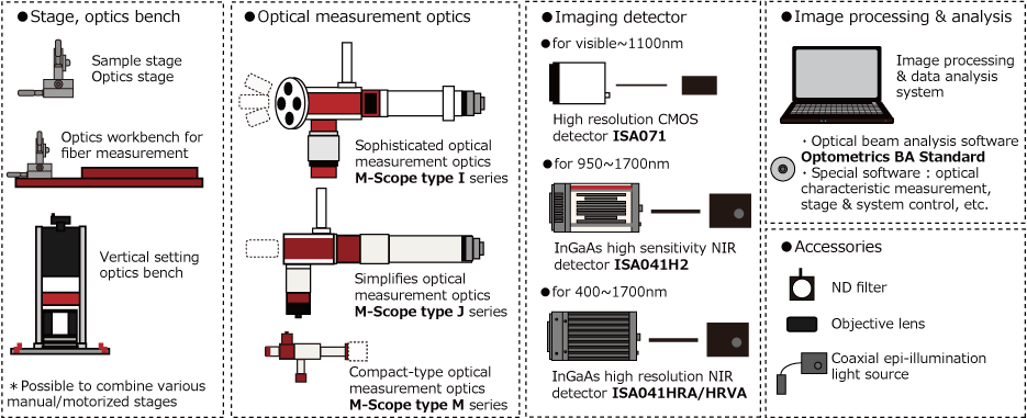
STANDARD COMPONENT
- M-Scope type J(optics unit) : 1set
- Standard optics unit(optical fiber connection port, coaxial epi-illumination port)
- Optical fiber connect port (Irradiate and detect with 1:1 optical fiber core diameter when using a 10x objective lens)
- Intermediate lens : 1×
- Coaxial epi-illumination port(outer diameter 8mmφ)
- Base plate for optics : 1set
OPTION
- Dedicated optional unit for M-Scope type J
- Customization of M-Scope type I
- Customization of optical fiber connect port, image detector port
- Specification change of built-in optical parts (mirror, lens, etc.)
- Customization of light irradiation and detection magnification ratio, etc.
- Please contact us for customizing the optical system.
- Variable Spot Size Converter Unit MS-OP012-VFPJ
- Fiber port that can continuously change irradiation and detection diameter. The continuous variable range is as follows.
- Objective lens 10×: irradiation and detection with 1.11 to 3.33 times the equivalent diameter of the connected optical fiber core
- Objective lens 20×: irradiation and detection with 0.55 to 1.66 times the equivalent diameter of the connected optical fiber core
- Objective lens 50×: irradiation and detection with 0.22 to 0.66 times the equivalent diameter of the connected optical fiber core
- Detector
- Wavelength range : 400~1100nm
- Wavelength range : 950~1700nm
- Wavelength range : 400~1700nm
- InGaAs High Resolution NIR Detector ISA041HRA/ISA041HRVA.
- About imaging detector selection, please refer to here.
- Objective lens
- M-Plan Apo series
- About objective lens, please refer to here.
- Neutral density filter
- About neutral density filters, please refer to here.
- Measurement light source
- About measurement light source, please refer to here.
- Various types of light source unit on the market is also available.
- Coaxial Epi-illumination Light Source
- About coaxial epi-illumination light source, please refer to here.
- Optics workbench for sample measurement
- Optics Bench For Fiber Measurement OP002-F3/OP002-F5
- Vertical Type Optics Bench OP002
- About optics workbench, please refer to here.
ADVANCED PRODUCT
POLARIZATION COMPENSATION TYPE SIMPLIFIED OPTICAL MEASUREMENT OPTICS M-Scope type J/PF
POLARIZATION COMPENSATION TYPE SIMPLIFIED OPTICAL MEASUREMENT OPTICS M-Scope type J/PF
When the measurement is performed using a single-mode fiber for introduction and irradiation of measurement light, it may apply pressure on optical fiber from the external influence. In this case, it may change the polarization status in single-mode fiber, the stability of the measurement accuracy would be degraded in the entire measurement system. In case using half mirror(HM) in the optical system branching 2 or 3, when measuring the sample having such polarization characteristics, it may affect the measurement results due to polarization characteristics of the HM.
M-Scope type J/PF is the optical system that achieves stable and high precision measurements even when the measurement sample has such polarization characteristics by removing the effects of polarization with special position of a half mirror.
POLARIZATION COMPENSASION OF HALF MIRROR
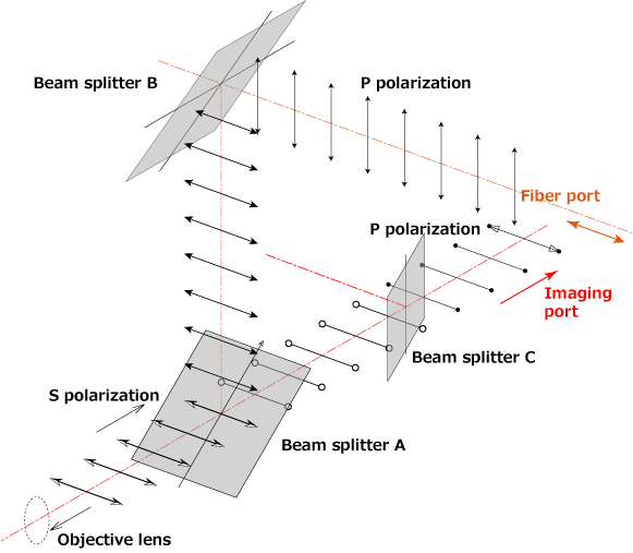
Half mirror used for splitter has different transmittance and reflectance depending on the polarization direction. For this reason, the polarization state during irradiation and reception may affect the measurement.
Our polarization compensation optics has the structure that compensates for polarization dependence of the half mirror by arrangement structure as shown in the left figure.
OUTSIDE DIMENSIONS
OUTSIDE DIMENSIONS OF M-Scope type J
- Please ask the drawing data in details of M-Scope type J/PF if necessary.
- Outside dimensions above is reference values. These values change as equipped option and detector. Please ask the drawing data in details if necessary.
TECHNICAL INFORMATION
- About light irradiation and detection measurement by optical method
- (FILE No. C-1)What is "optical beam irradiation and detection measurement using optical system"?
- There is an explanation about light irradiation measurement and light reception measurement using an optical system.