OPTICAL CONTINUITY TESTER
PRODUCT OVERVIEW
OPTICAL CONTINUITY TESTER
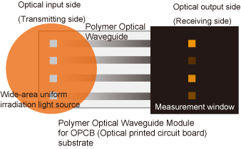
MEASUREMENT METHOD OF OPTICAL CONTINUITY TESTER
FEATURE
- Optical continuity tester with one-shot irradiation system for measurement light as mass production inspection compliant.
- Newly developed one-shot irradiation system for measurement light and high NA detection optical system should realize high speed and high accuracy test.
- Extraction, processing and automatic measurement only for propagation optical intensity signal from optical waveguide with proprietary software.
- In combination with high precision motorized stage system, it is possible to execute additional function such as defocusing mode measurement, core shape / pitch / position measurement, full-automatic measurement system and so on.
APPLICATION
- High-speed optical continuity test for polymer optical waveguide for OPCB substrate at mass production.
- Pass/Fail judgement of continuity condition by relative loss measurement and comparison with reference.
- Defocus measurement
- Area intensity measurement at virtual position of detector.
- Core pitch measurement
- Core position measurement
- Inclination measurement of 45° built-in mirror in polymer waveguide.
SYSTEM COMPONENT SELECTION
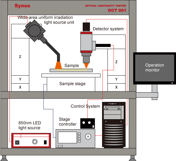
SYSTEM CONFIGURATION DIAGRAM
COMPONENT SELECTION
- Wide area uniform light irradiation unit
- Output N.A. : 0.57
- Irradiation size : approx.φ4mm (@5mm gap)
- Uniformity in irradiation surface : ±2%
- Light source : 850nmLED
- Center wavelength of light source : 850nmLED (FWHM:±40nm)
- Maximum output power : approx. 15mW
- Output light stability : ±1%
- Dedicated large N.A. measurement optics
- Detection N.A. : 0.4
- Optical magnification : 5× (20× objective lens is used)
- Field of view : 1.28mm×0.96mm
- Detector
- 400~1100nm: High Resolution CMOS Detector ISA071
- Total pixels : 2048×1536 pixels (approx. 3.2 megapixels)
- Pixels pitch : 3.45×3.45μm
- Sensor size : 1/1.8 inch
- Gradation : 12bit
- Stage system
- Stage system for input side light irradiation unit
- Stage system for output side measurement optics
- System platform, bracket, etc,
- Sample stage
- Sample stage
- Sample holder
- System Control
- Computer for data processing and system control
- Monitor for operation
- Control and analysis software for Optical Continuity Tester
- Stage control system
- System main control unit
- System power supply unit
- Safety equipment etc.
- Incidental facilities
- Shield box
- Vibration isolated stage
- *Configuration written above is a standard example, and we can deliver any configuration according to the applications.